Conventions and Coordinate Systems
This document describes the conventions and coordinate systems used in the Vantor Raptor Guide SDK for high-precision camera pose estimation.
Terrestrial Reference Frame
What is a Terrestrial Reference Frame?
A Terrestrial Reference Frame (TRF) is a coordinate system that is fixed to the Earth's surface and rotates with the Earth. It provides a standardized way to define positions on or near the Earth's surface with high precision.
ITRF2008 vs WGS84 with Different Realizations
The Raptor Guide SDK uses ITRF2008 (International Terrestrial Reference Frame 2008) as its terrestrial reference frame, which is approximately equivalent to specific WGS84 realizations:
- ITRF2008 ≈ WGS 84 G1674 (approximate equivalence within centimeters)
- ITRF2008 = WGS 84 G1762 (approximate equivalence within millimeters)
Key Differences:
- ITRF2008: A scientific reference frame maintained by the International Earth Rotation and Reference Systems Service (IERS)
- WGS84: A practical reference system used by GPS, with multiple realizations (G1674, G1762, etc.)
- The SDK's choice of ITRF2008 ensures compatibility with high-precision geodetic applications
Spatial Reference Frames
ECEF (Earth-Centered Earth-Fixed)
ECEF is a 3D Cartesian coordinate system with its origin at the Earth's center of mass.
Coordinate Definition:
- Position: [X, Y, Z] in meters from Earth's center
- X-axis: Points toward the intersection of the equator and prime meridian (0° latitude, 0° longitude)
- Y-axis: Points toward 90° East longitude on the equator
- Z-axis: Points toward the North Pole
- Attitude: Rotation relative to ECEF X, Y, Z axes
Use Cases:
- Satellite data processing
- Global positioning systems
- Applications requiring a single global coordinate system
Geodetic
Geodetic coordinates use latitude, longitude, and height relative to a reference ellipsoid.
Coordinate Definition:
- Position: [Latitude(rad), Longitude(rad), Height(m)]
- Latitude: Angular distance north/south from the equator (-π/2 to π/2 radians)
- Longitude: Angular distance east/west from the prime meridian (-π to π radians)
- Height: Height above the WGS84 ellipsoid in meters
- Attitude: Rotation relative to local North-East-Down (NED) frame
Use Cases:
- GPS coordinates and navigation
- Aviation applications
- Recommended when covariance matrix is provided (pose search in north-east plane is more robust than in ECEF)
NED (North-East-Down)
NED is a local cartesian coordinate system used in navigation and aerospace applications. The NED convention follows the DIN 9300 standard, where the x-axis points towards the north, the y-axis points towards the east, and the z-axis points downwards. North in this case is considered to be the true/geographic north, and not the magnetic north.

NED convention with axes named according to the standard DIN 9300
Attitude Representation
Overview of Attitude Representations
The attitude of the camera is represented as a rotation from the reference frame to the camera frame, i.e. attitude of the camera frame relative to the reference frame. These rotations can be represented in various forms, each with its own advantages and disadvantages. In the interface of the SDK the attitude is represented as a unit quaternion. In the guide below we also use rotation matrices and Euler angles to demonstrate the transformations between different coordinate frames.
1. (Unit) Quaternions
- Format: [x, y, z, w] (scalar component w last)
- Advantages: No singularities, compact representation, efficient composition
- Use: Attitude representation used in the interface of the SDK
2. Direction Cosine Matrix (DCM) / Rotation Matrix
- Format: 3×3 orthogonal matrix
- Advantages: Direct geometric interpretation, no singularities, convenient for rotating between different frames using matrix multiplication
- Disadvantages: Redundant information with 9 elements (only 3 degrees of freedom)
- Use: Internal calculations and frame transformations
3. Euler Angles
- Format: Yaw-Pitch-Roll (Z-Y-X rotation sequence)
- Advantages: Intuitive interpretation
- Disadvantages: Gimbal lock at ±90° pitch. Order of appliance is critical and may lead to ambiguities.
- Use: Human-readable attitude representation
Rotation Sequence: Reference Frame to Camera Frame
To determine the attitude of the camera relative to the reference frame, we need to apply a sequence of rotations between different cartesian coordinate frames. Rotations between multiple frames are combined by multiplying the individual rotation matrices for each frame-to-frame rotation (chain-rule). That means that we can describe the complete transformation from reference frame to camera frame as a single rotation matrix .
The transformation from reference frame to camera frame follows this sequence:
- Reference Frame (ECEF or Local NED)
- Intermediate transformations (if applicable)
- Platform Frame (aerial vehicle body frame)
- Camera Frame (sensor-specific orientation)
In the SDK the DIN 9300 standard axes convention is applied even for the camera, and therefore also the image plane of the camera, meaning that the x-axis points forward, the y-axis to the right, and the z-axis downward in the image.
Step-by-Step Frame Conversion Guide
In this guide we will use Rotation Matrices to demonstrate the transformations between different coordinate frames. The combined transformation from the reference frame to the camera frame is then obtained by multiplying the individual rotation matrices together. In the final step we will convert the resulting rotation matrix to a quaternion that can be used as input to the SDK.
The guide uses ECEF as reference frame. The ECEF to local NED transformation is therefore not necessary when Geodetic reference frame is used in the SDK.
The complete transformation from ECEF to Camera Frame can be expressed as the following sequence of matrix multiplications:
1. ECEF to Local NED
Purpose: Transform from global Earth-fixed coordinates to local navigation frame.
The DCM for ECEF to Local NED () can be computed using the geodetic coordinates (lat-long).
Mathematical Transformation:
where is latitude and is the longitude.
Steps:
- Convert ECEF position [X, Y, Z] to geodetic [lat, lon, height]
- Compute local NED axes matrix at the geodetic location
2. Local NED to Platform (Aerial Vehicle)
Purpose: Transform from navigation frame to vehicle body frame.
Navigation System Context: It is standard practice for navigation systems (GPS/IMU, flight management systems, etc.) to describe the attitude of an aerial vehicle with respect to the local NED frame using yaw, pitch, and roll angles. These may be provided under different terminology:
- Yaw (also called heading, azimuth, or bearing)
- Pitch (also called elevation or nose-up/down angle)
- Roll (also called bank angle or wing-up/down angle)
Using Navigation System Outputs: If your navigation system provides attitude as yaw, pitch, and roll angles relative to local NED, you can directly use these values to construct the Local NED to Platform transformation matrix.
Euler Angle Sequence (Z-Y-X):
- Yaw (Z-axis rotation): Rotation about the down axis (heading direction)
- Pitch (Y-axis rotation): Rotation about the lateral axis (nose up/down)
- Roll (X-axis rotation): Rotation about the longitudinal axis (wing up/down)
Rotation Matrix Construction:
Example Usage:
// Navigation system outputs (in radians)
double yaw = navigation_system.getHeading();    // or getYaw(), getAzimuth()
double pitch = navigation_system.getPitch();    // or getElevation()
double roll = navigation_system.getRoll();      // or getBankAngle()

// Construct rotation matrix from NED to platform frame
Matrix R_ned_to_platform = eulerZYX(yaw, pitch, roll);
3. Platform to Camera
Purpose: Transform from vehicle body frame to camera sensor frame.
Camera Mounting Context:
Visual-based navigation systems typically use camera sensors that are mounted to the platform in one of two configurations:
- Fixed mount: Camera rigidly attached to the platform with a known, constant orientation
- Gimbal mount: Camera mounted on a stabilized gimbal system that can rotate independently
This transformation describes the camera mount orientation relative to the platform frame, which depends on your specific camera installation.
Common Fixed Mount Examples:
Platform Frame Convention (DIN 9300):
- X-axis: Forward (nose direction)
- Y-axis: Right (starboard direction)
- Z-axis: Down (toward ground)
- Yaw: Rotation about Z-axis (left/right turn)
- Pitch: Rotation about Y-axis (nose up/down)
- Roll: Rotation about X-axis (wing up/down)
-
Nadir-looking camera (straight down):
// Camera looking straight down from platform
// 90° pitch rotation (about Y-axis) to point camera X-axis downward
// 90° roll rotation (about X-axis) to align image width with platform X-axis
double yaw = 0.0;                            // 0° - no left/right rotation
double pitch = usage_utils::degreesToRadians(90.0);  // 90° - nose down rotation
double roll = usage_utils::degreesToRadians(90.0);   // 90° - rotate image orientation
Matrix R_platform_to_camera = eulerZYX(yaw, pitch, roll);
Image Coordinate Alignment: For this nadir-looking camera configuration, the image dimensions are aligned with the platform coordinate axes as follows:
- Image width (horizontal pixels) → aligned with platform X-axis (forward/aft direction)
- Image height (vertical pixels) → aligned with platform Y-axis (left/right direction)
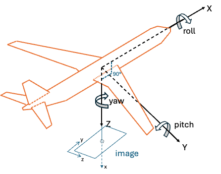
Illustration of camera mounted to look straight down
- Forward-looking camera (45° down from horizontal):
// Camera looking forward and 45° down from platform
// 45° pitch rotation (about Y-axis) for downward tilt
double yaw = 0.0;                            // 0° - no left/right rotation
double pitch = usage_utils::degreesToRadians(45.0);  // 45° - slight nose down
double roll = 0.0;                           // 0° - no wing rotation
Matrix R_platform_to_camera = eulerZYX(yaw, pitch, roll);
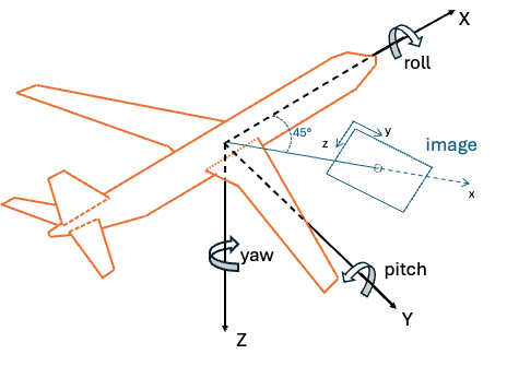
Illustration of camera mount with 45° downward tilt
Implementation Considerations:
- Fixed mounts: Use constant rotation matrix based on mechanical mounting angles
- Gimbal systems: Rotation matrix varies based on gimbal position (requires real-time gimbal angle data)
- Calibration: Mount angles should be precisely measured or calibrated
- Coordinate conventions: Ensure camera frame follows DIN 9300 standard (X-forward, Y-right, Z-down)
(Optional) Platform to Image Plane to Camera frame
Raptor Guide expects a camera frame where the axes of the coordinate system is x=forward (in image), y=right, z=down (DIN 9300 standard). Therefore, an extra transformation might be needed if first transforming from Platform frame to the standard pixel coordinate frame before converting to the camera frame. This is not needed if the image plane already follows the DIN 9300 standard.
Image Plane Convention: In computer vision, the image plane is often defined with the following convention:
- X-axis: Rightward in the image
- Y-axis: Downward in the image
- Z-axis: Outward from the image plane (towards the camera)
Rotation Matrix to Quaternion Conversion
From Rotation Matrix R to Quaternion [x, y, z, w]:
double trace = R[0][0] + R[1][1] + R[2][2];

if (trace > 0) {
    double s = sqrt(trace + 1.0) * 2; // s = 4 * w
    w = 0.25 * s;
    x = (R[2][1] - R[1][2]) / s;
    y = (R[0][2] - R[2][0]) / s;
    z = (R[1][0] - R[0][1]) / s;
} else if (R[0][0] > R[1][1] && R[0][0] > R[2][2]) {
    double s = sqrt(1.0 + R[0][0] - R[1][1] - R[2][2]) * 2; // s = 4 * x
    w = (R[2][1] - R[1][2]) / s;
    x = 0.25 * s;
    y = (R[0][1] + R[1][0]) / s;
    z = (R[0][2] + R[2][0]) / s;
}
// ... additional cases for numerical stability
Complete Example: Navigation System to SDK Quaternion
This section provides a complete walkthrough showing how to transform navigation system outputs into the quaternion format required by the usage_examples/advanced_usage.cpp example. We'll demonstrate the full pipeline from GPS/IMU data to the final camera attitude quaternion using the Geodetic reference frame.
Navigation System Input Data
Assume your navigation system provides the following data for image 000.jpeg:
Position from GPS (Geodetic coordinates):
double latitude = 39.0945;   // degrees North
double longitude = -77.5655; // degrees West
double altitude = 295.0;     // meters above WGS84 ellipsoid
Platform Attitude from IMU (relative to local NED):
double platform_yaw = 135.0;   // degrees (heading)
double platform_pitch = -20.0; // degrees (nose down)
double platform_roll = 10.0;   // degrees (right wing down)
Camera Mount Configuration: The camera is mounted looking straight down with image width aligned with platform X-axis (as per the nadir example above):
- 90° pitch rotation to point downward
- 90° roll rotation for image alignment
Step-by-Step Transformation Pipeline
Step 1: Convert Navigation System Data to Radians
Position Conversion:
// Convert geodetic coordinates to radians (for Geodetic reference frame)
double lat_rad = usage_utils::degreesToRadians(39.0945);  // 0.6822 radians
double lon_rad = usage_utils::degreesToRadians(-77.5655); // -1.3537 radians
double height = 295.0;                                    // meters

// For usage_examples/advanced_usage.cpp (uses Geodetic reference frame)
std::array<double, 3> geodetic_position = {lat_rad, lon_rad, height};
// Result: [0.6822, -1.3537, 295.0] (lat, lon, height)
Platform Attitude Conversion:
// Convert platform attitude from degrees to radians
double yaw_rad = usage_utils::degreesToRadians(135.0);    // 2.356 radians
double pitch_rad = usage_utils::degreesToRadians(-20.0);  // -0.349 radians
double roll_rad = usage_utils::degreesToRadians(10.0);    // 0.175 radians
Step 2: Create Platform Attitude Matrix (NED to Platform)
Construct rotation matrix from navigation system Euler angles:
// Platform attitude relative to local NED frame
Matrix R_ned_to_platform = eulerZYX(yaw_rad, pitch_rad, roll_rad);

// Resulting matrix for yaw=135°, pitch=-20°, roll=10°:
R_ned_to_platform = [-0.6634  -0.7431   0.0868]
                    [ 0.7071  -0.6830   0.1837]
                    [-0.2419   0.3420   0.9397]
Step 3: Create Camera Mount Matrix (Platform to Camera)
Apply camera mounting transformation:
// Camera mount: 90° pitch + 90° roll (nadir with width aligned to platform X-axis)
double camera_yaw = 0.0;                                 // 0° - no rotation about Z
double camera_pitch = usage_utils::degreesToRadians(90.0);  // 90° - point downward
double camera_roll = usage_utils::degreesToRadians(90.0);   // 90° - align image width with X

Matrix R_platform_to_camera = eulerZYX(camera_yaw, camera_pitch, camera_roll);

// Resulting matrix:
R_platform_to_camera = [ 0.0000   0.0000   1.0000]
                       [ 0.0000   1.0000   0.0000]
                       [-1.0000   0.0000   0.0000]
Step 4: Combine All Transformations
Calculate complete transformation from NED to Camera:
// Chain the transformations: NED → Platform → Camera
Matrix R_ned_to_camera = R_ned_to_platform * R_platform_to_camera;

// Matrix multiplication result:
R_ned_to_camera = [-0.6634  -0.7431   0.0868] × [ 0.0000   0.0000   1.0000]
                  [ 0.7071  -0.6830   0.1837]   [ 0.0000   1.0000   0.0000]
                  [-0.2419   0.3420   0.9397]   [-1.0000   0.0000   0.0000]

R_ned_to_camera = [ 0.0868  -0.7431  -0.6634]
                  [ 0.1837  -0.6830   0.7071]
                  [ 0.9397   0.3420  -0.2419]
Step 5: Convert to Quaternion for SDK
Convert the final rotation matrix to quaternion [x, y, z, w]:
Matrix R = R_ned_to_camera;
double trace = R[0][0] + R[1][1] + R[2][2];

// For our matrix: trace = 0.0868 + (-0.6830) + (-0.2419) = -0.8381
// Since trace < 0, use alternative method for numerical stability

double x, y, z, w;
// Find largest diagonal element
if (R[0][0] > R[1][1] && R[0][0] > R[2][2]) {
    double s = sqrt(1.0 + R[0][0] - R[1][1] - R[2][2]) * 2; // s = 4 * x
    w = (R[2][1] - R[1][2]) / s;
    x = 0.25 * s;
    y = (R[0][1] + R[1][0]) / s;
    z = (R[0][2] + R[2][0]) / s;
}
// ... additional cases handled similarly

// Final quaternion for usage_examples/advanced_usage.cpp (Geodetic reference frame):
std::array<double, 4> camera_attitude = {x, y, z, w};
// Result: [0.683498, 0.275160, 0.590605, -0.329093]
Summary: Navigation System to SDK Pipeline
Complete transformation chain:
- Navigation System Outputs: GPS position + IMU Euler angles (relative to NED)
- Position: Use geodetic coordinates directly (for Geodetic reference frame)
- Platform Attitude: Convert Euler angles → rotation matrix (NED to Platform)
- Camera Mount: Apply fixed mount transformation (Platform to Camera)
- Combined Transformation: Multiply matrices (NED to Camera)
- Final Quaternion: Convert rotation matrix → quaternion for SDK
Key Points:
- The SDK receives the camera attitude relative to the reference frame (local NED in this example)
- Navigation system provides platform attitude relative to NED
- Camera mount transformation accounts for physical camera installation
- Final quaternion represents the complete transformation chain
- Geodetic reference frame: Position stays in lat/lon/height, attitude is relative to local NED
This pipeline allows you to use standard navigation system outputs directly with the Raptor Guide SDK by properly accounting for coordinate frame transformations and camera mounting geometry.
Other SDK Conventions
Data Format
- Matrix Storage: Row-major order for all matrices and images
- Angular Units: Radians for all internal calculations
- North Reference: True north (not magnetic north)