Conventions and Coordinate Systems
This document describes the geodetic and attitude conventions used by the Raptor SDK. For the API-side view of how these are configured on a pose, see the Integration Guide.
Reference Frame
The SDK uses ITRF2008 (International Terrestrial Reference Frame 2008) as its default reference frame. It is equivalent to WGS 84 G1762 within millimetres and to WGS 84 G1674 within centimetres.
Coordinate Systems
The SDK supports two coordinate systems: ECEF and Geodetic.
ECEF (Earth-Centered Earth-Fixed)
A 3D Cartesian system with its origin at Earth's centre of mass:
- X-axis: equator × prime meridian (0° lat, 0° lon)
- Y-axis: equator at 90° E
- Z-axis: North Pole
- Coordinates:
[X, Y, Z]in meters - Attitude: rotation relative to the ECEF X/Y/Z axes
Geodetic
Latitude, longitude and height above a reference surface (positive up):
- Latitude: north/south of the equator, range
[-π/2, π/2](radians) or[-90°, 90°] - Longitude: east/west of the prime meridian, range
[-π, π](radians) or[-180°, 180°] - Altitude: height above the reference surface, positive upward
- Attitude: rotation relative to the local NED frame at the position
NEU vs NED
NEU labels the lat, lon, alt ordering of the position components on
the coords field of position::Geodetic / pose::Geodetic (altitude
positive up) — it is an ordering, not a Cartesian frame. Attitude on a
geodetic pose is always relative to the local NED tangent-plane frame
defined below.
Height System (Vertical Datum)
Two height systems are supported:
- Ellipsoid (HAE — Height Above Ellipsoid): height perpendicular to the WGS84 ellipsoid. GPS/GNSS receivers natively output ellipsoid heights.
- EGM2008 (Orthometric / HAMSL): height perpendicular to the EGM2008 geoid, which approximates mean sea level. Surveyed elevations, topographic maps and barometric altimeters typically reference the geoid.
NED (North-East-Down)
NED is the local tangent-plane frame used for attitude on geodetic poses and as the intermediate frame in the rotation chain below. It follows the DIN 9300 convention: x → north, y → east, z → down. North refers to the true/geographic north, not the magnetic north.

NED convention with axes named according to the standard DIN 9300
Attitude Representation
The SDK takes camera attitude as a unit quaternion [x, y, z, w]
(scalar component last) representing the rotation from the reference frame
to the camera frame. The derivations below use rotation matrices and Euler
angles only as intermediate steps; convert the final rotation matrix to a
quaternion before passing it to the SDK.
Euler angles in this guide follow the Z-Y-X (yaw-pitch-roll) intrinsic sequence. The camera frame itself follows the DIN 9300 convention (x-forward in the image, y-right, z-down), the same convention used for the platform frame.
Pick whichever CRS your nav system produces
Pass pose::Geodetic if your nav system gives lat/lon/height with attitude
relative to local NED (the usual GPS/IMU output). Pass pose::Ecef if it
gives ECEF position with attitude relative to the ECEF axes. The SDK
converts between the two internally via raptor::geo::convert, including
the local NED ↔ ECEF rotation of the attitude — you do not need to apply
that rotation yourself.
The rest of this section derives the rotation chain for reference, e.g. if you need to inspect or debug attitude outside the SDK, or build a quaternion by hand from raw yaw/pitch/roll plus a camera mounting.
Frame Conversion: Reference Frame to Camera Frame
The camera attitude is composed from successive frame rotations:
- Reference frame (ECEF or local NED) → Platform / body frame → Camera frame
The derivation below uses ECEF as the reference frame. For a Geodetic pose the attitude is already relative to local NED, so the ECEF→NED step drops out.
The complete transformation is:
1. ECEF to local NED
The NED-to-ECEF rotation depends only on latitude and longitude . Its columns are the local N, E and D axes expressed in ECEF:
If the position is given in ECEF, convert it to geodetic first to obtain and .
2. Local NED to platform (body frame)
Navigation systems (GPS/IMU, flight management systems) typically express platform attitude as yaw, pitch and roll angles relative to local NED. Synonyms you may encounter:
- yaw — heading, azimuth, bearing
- pitch — elevation, nose-up/down
- roll — bank, wing-up/down
The Z-Y-X intrinsic composition gives:
// Navigation system outputs (radians)
Matrix R_ned_to_body = eulerZYX(yaw, pitch, roll);
3. Platform to camera
Encodes the camera's mounting orientation in the platform frame. For a fixed mount this is a constant matrix derived from the mechanical mounting angles; for a gimbal mount it varies with the gimbal state and must be supplied per frame.
Example — nadir-looking camera (straight down):
// 90° pitch points the camera X-axis (forward in the image) downward;
// 90° roll aligns the image width with the platform X-axis.
double yaw   = 0.0;
double pitch = degreesToRadians(90.0);
double roll  = degreesToRadians(90.0);
Matrix R_body_to_cam = eulerZYX(yaw, pitch, roll);
For this mount, image width aligns with the platform X-axis (forward/aft) and image height with the platform Y-axis (left/right).
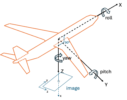
Nadir-looking camera
Example — forward-looking camera, 45° down from horizontal:
double yaw   = 0.0;
double pitch = degreesToRadians(45.0);
double roll  = 0.0;
Matrix R_body_to_cam = eulerZYX(yaw, pitch, roll);
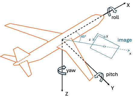
Forward-looking camera with 45° downward tilt
Image-plane convention (only if your pipeline uses a different one)
The SDK's camera frame follows DIN 9300: x-forward (into the image), y-right, z-down. If an upstream stage produces poses in the typical computer-vision image frame (x-right, y-down, z-out of the image), apply the corresponding fixed rotation before passing the result to the SDK.
Rotation matrix to quaternion
Convert the combined rotation matrix to a unit quaternion using any
numerically stable routine. The SDK consumes the result as [x, y, z, w] with the
scalar component last.
Putting it together
The attitude quaternion carried by each pose type encodes:
pose::Geodetic:pose::Ecef:
In practice, supply whichever form your nav system produces and let the SDK convert; you only need to build the chain by hand if you are constructing a pose outside the SDK or validating its contents.
A runnable end-to-end example that converts navigation-system outputs
(GPS + IMU yaw/pitch/roll + fixed camera mount) into the SDK's pose
structure is shipped in examples/guide/.
Other SDK Conventions
Data Format
- Matrix Storage: Row-major order for all matrices and images
- Angular Units: Radians for all internal calculations
- North Reference: True north (not magnetic north)