Main view
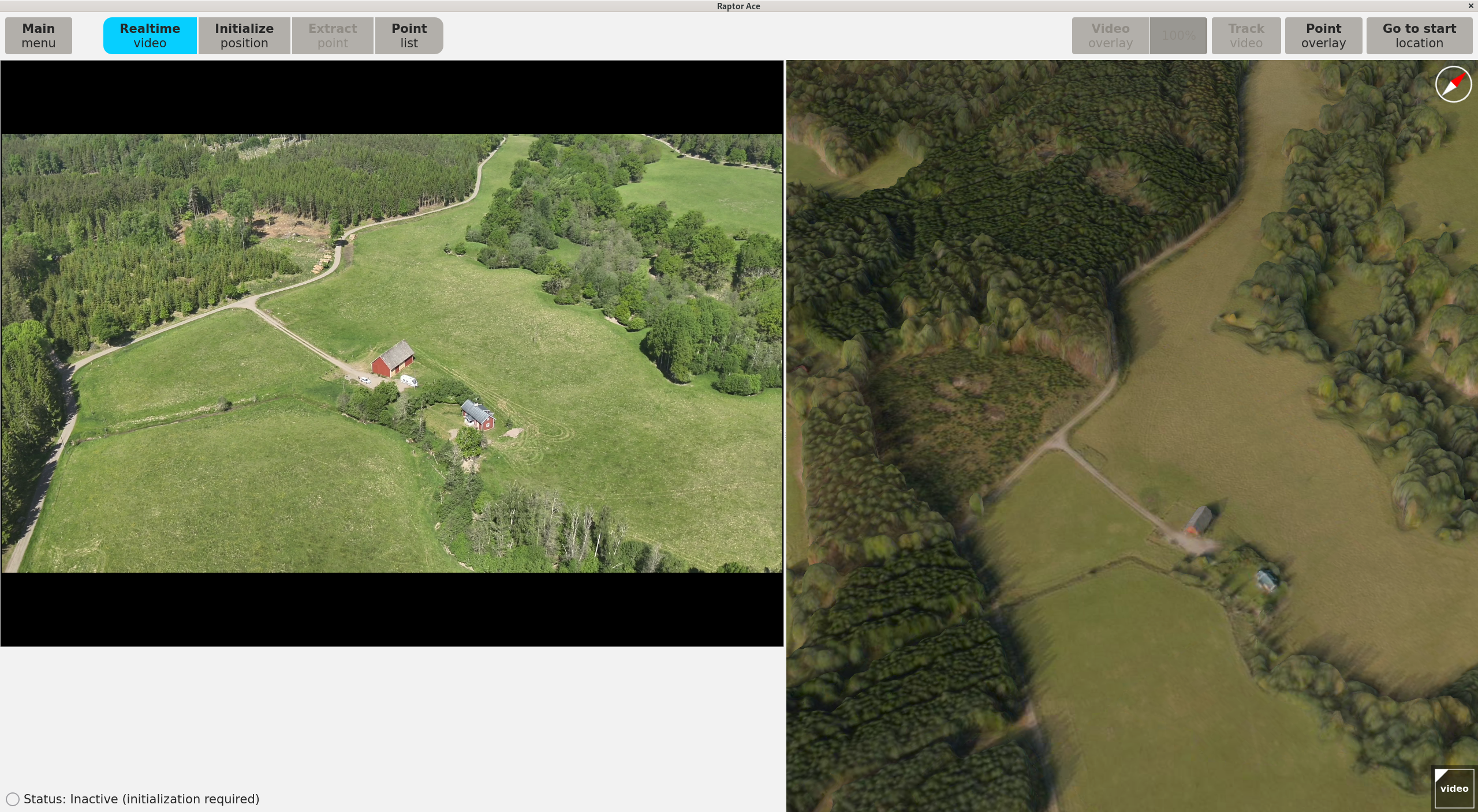
Hover over the image to highlight components of the Raptor Ace layout.
The core components of the Raptor Ace main view are the video panel, the 3D data panel, and the menu bar with dedicated functions for each panel.
Application navigation
To navigate the 3D data and video panel
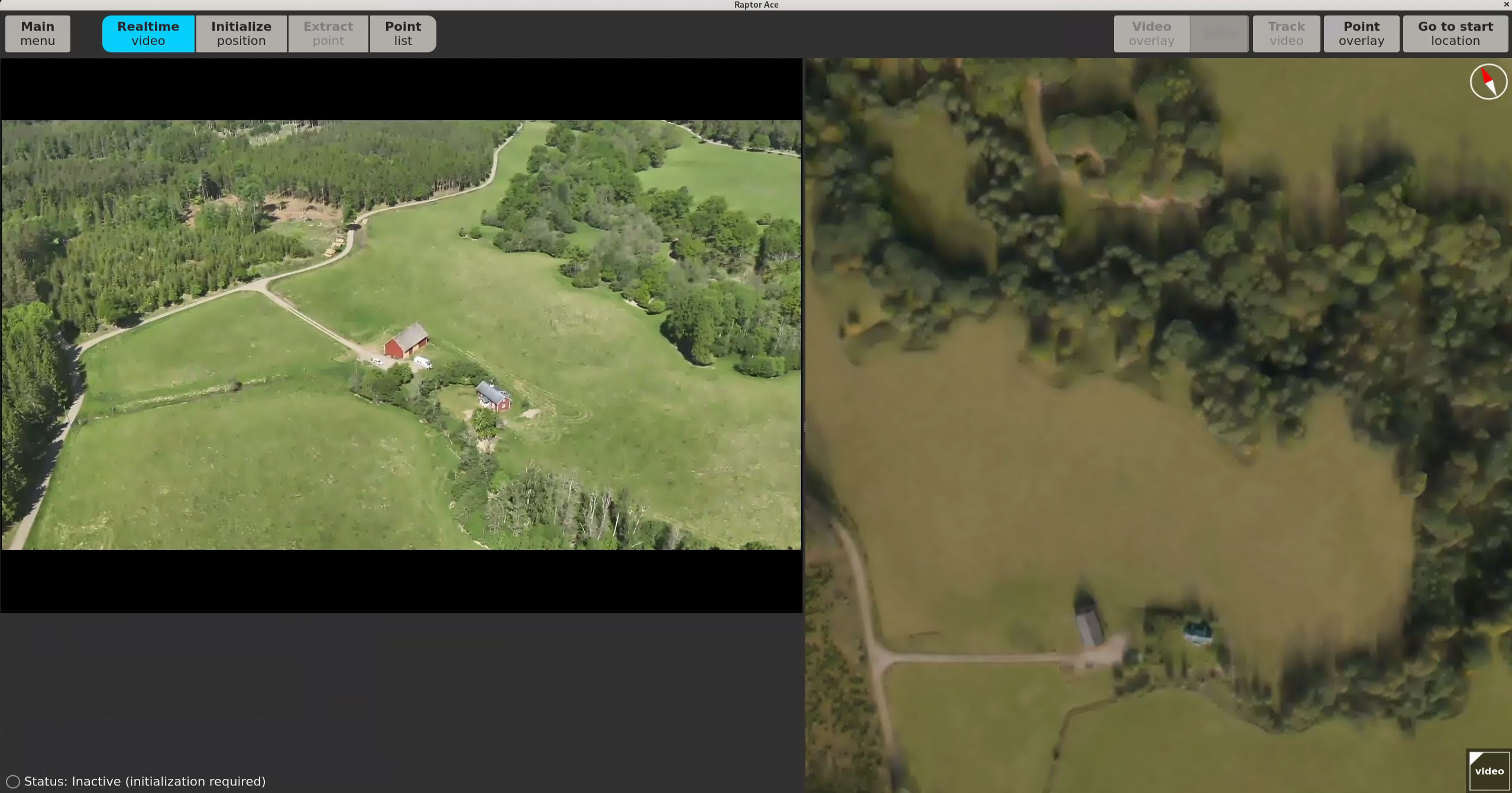
- Drag the line in the middle of the screen to adjust the sizes of the video panel and the 3D data panel.
- Click and hold the right mouse button and move the mouse to rotate the 3D data panel around the mouse pointer.
- Click and hold the left button and move the mouse to pan in the 3D data panel.
- To zoom in the 3D data panel:
- Use the mouse scroll wheel.
- Click and hold the middle button and move the mouse up or down.
- To zoom in the video panel:
- Use the mouse scroll wheel.
- Click Reset zoom to return to the default view.
To go back to main menu
- Click Main menu in the menu bar to return to the main menu and modify settings.
3D data panel
- If a start position is selected, the 3D reference data starts from the position.
- If no start position is selected, the 3D reference data panel shows the whole extent.
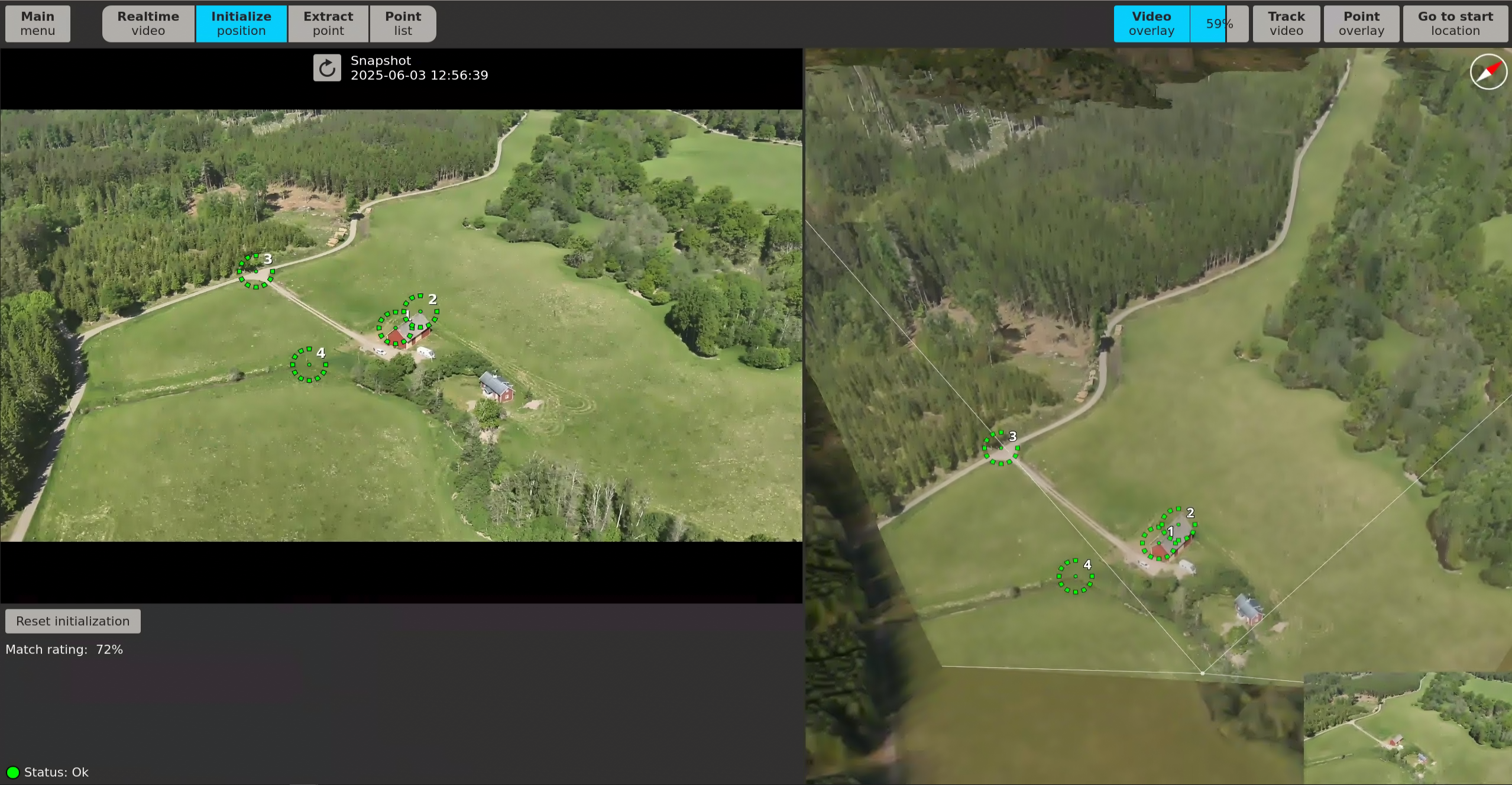
To enable video overlay
- Click Video overlay to view the video layered on top of the 3D reference data.
- Click and drag the slider to adjust the opacity of the video projection.
To enable video tracking
- Click Track video to follow the video at the correct angle throughout the 3D reference data, based on your position, to see how well it aligns with the 3D reference data.
- Press + or — to zoom in or out of the video tracking view.
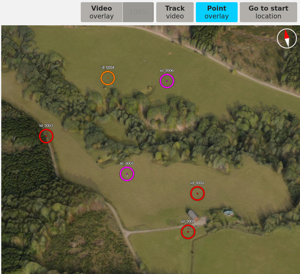
To enable point overlay
- Click Point Overlay to see the saved points in the 3D reference data.
To navigate to start position
- Click Go to start location to navigate to the selected start location.
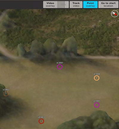
To enable overview of video
- Click the miniature video icon in the bottom right corner to show the video in the corner of the 3D reference data.
- Click the icon again to hide the video.
For navigation, enable Video Overlay and adjust the opacity as needed, then enable Track video to both display and follow the video feed across the 3D reference data.
Video panel
Realtime video
Click Realtime video to view the live drone video.
If the drone loses connection, an error message stating Connection to drone lost is displayed. Return to Video in main menu and click on Connect to reconnect the drone.
Initialize position
To properly operate, Raptor Ace first needs an initial pose (position and attitude) of the drone’s sensor. The initialization is performed after takeoff to ensure the drone video accurately corresponds to the 3D reference data.
To start an initialization
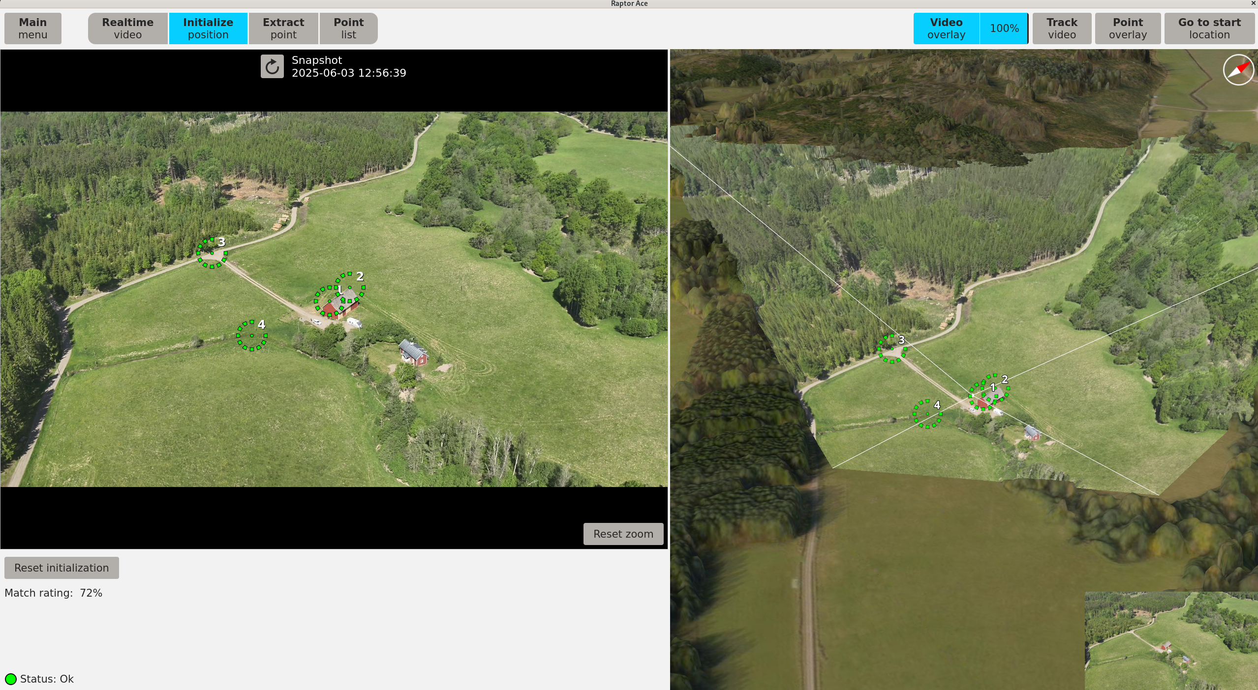
- Hover the drone and fix the sensor field-of-view on a terrain segment with well-defined features that are identifiable in the video and 3D reference data.
- Click Initialize position when a suitable terrain segment is found.
- Place matching pairs of reference points by marking one point in the video and its corresponding point in the 3D reference data. Place the reference points on distinct features seen in both panels. Repeat this process until there is a minimum of three matching points. Recommended amount is at least four points.
- Yellow points don't have a matching point in the other panel.
- Green points have a matching point in the other panel.
- An estimation of the drone position is automatically done when there are three matching points. If a fourth matching point is added, a new estimation is done, and so on for each new matching point.
- Optional. Click ↻ Snapshot to update to a more recent video snapshot.
- Optional. Click Reset initialization to discard all the changes made.
- Proceed to Realtime video once manual verification of the initialization is completed.
To ensure accurate alignment, the reference points should be added to distinct features seen in both the video and the 3D reference data. For further alignment, reference points should be spatially distributed across the video and 3D reference data. Clustering points too closely or placing them along a single line may result in poor geometric coverage and lower alignment accuracy, due to it limiting the system’s ability to accurately estimate the positional relationship between the video and the 3D reference data.
- ⚪ Inactive (At least three reference points required)—Not enough reference points placed.
- 🟢 Ok—Match rating is sufficient, but always verify results manually.
- 🟡 Warning, low match rating—Match rating is low. Redo initialization.
The system provides a status indication to give a quick sense of the result’s quality. The Match rating indicator offers guidance on how well the drone video aligns with the 3D reference data at the time of initialization, but verification should always be performed manually. After placing the recommended amount of reference points, review the results in the 3D reference data. Review the results after each placed reference point. When the video overlay is accurately aligned with the 3D reference data, no additional reference points are needed.
- If the estimation does not meet your standards, a reinitialization can be performed until the results are satisfactory.
When initialization is performed, the drone must be still. Click Update snapshot if you notice the drone has drifted.
Extract point
Point extraction is done to retrieve exact coordinates in the world from the drone video. After an initialization is performed, to ensure the drone video corresponds to the 3D reference data, the coordinates of a point can be extracted.
To extract points
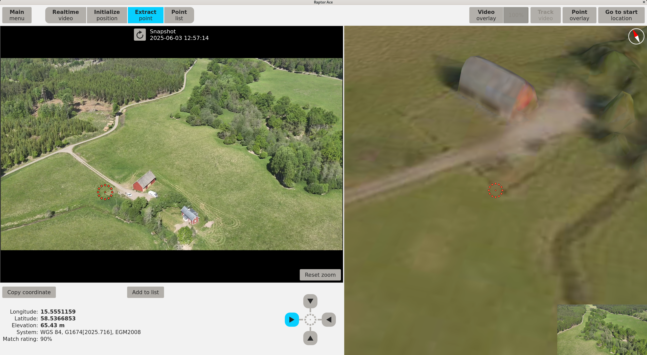
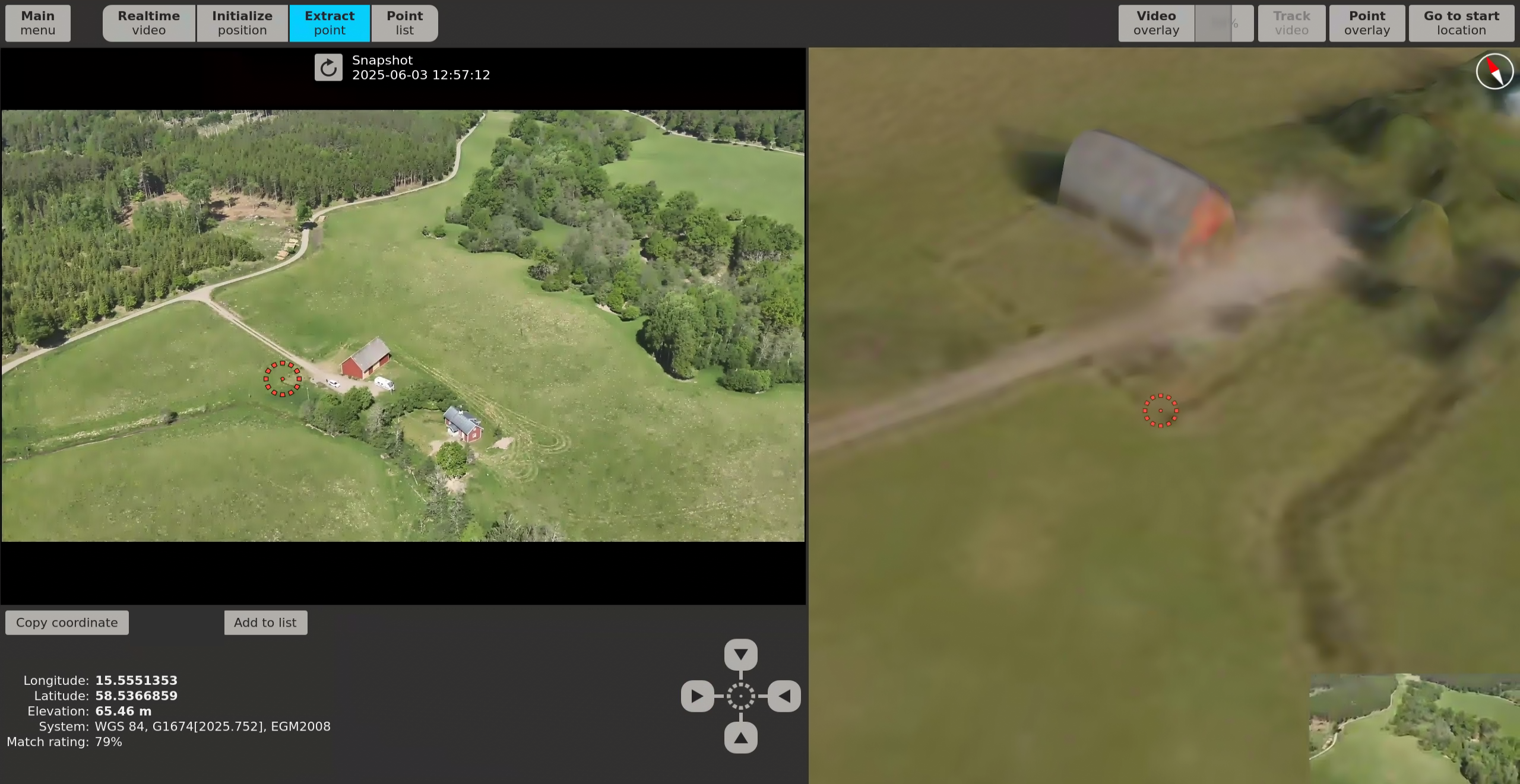
- Click Extract point to capture a snapshot of the identified point that is accepted for point extraction. Zoom in the video if needed before capturing the snapshot.
- Click in the video snapshot to precisely position a marker at the estimated terrain surface location of the point. For points that are not represented in the 3D surface model, such as vehicles, the marker should be positioned at the estimated terrain surface location of the footprint of the point.
- The coordinates of the point will be displayed below the video in the video panel.
- The 3D reference data will zoom in to the placed position.
- Press the directional keys


 or click the arrows in the video panel to view the point from different angles in the 3D reference data.
- Verify from a 3D view angle orthogonal to the snapshot panel angle that the point observation is located on the intended location in the 3D reference data. Small errors in the positioning of the marker or in the registration of the video can result in significant errors in the 3D point observation location that are not visible from the point of view of the snapshot.
- Verify that the 3D reference data and 3D point represent the current terrain surface and observation.
- Optional. Click Copy coordinate to copy the coordinate of the selected point to the clipboard.
- Click Add to list to add the verified and satisfactory point to the Point list.
Earthquakes that have occurred after 2005, due to tectonic plate movement, may introduce an error that is not compensated for in the coordinate epoch conversion. Raptor Ace will warn if a coordinate is extracted in a tectonic plate deformation zone. To verify accuracy of coordinates in deformation zones, a comparison with land survey equipment is recommended.
- 🟡 Warning, low match rating—Match rating is low. Consider refreshing the snapshot first, then redo the initialization if needed for better results.
- 🔴 Match rating too low—Point extraction is disabled when the match rating falls below 30%. Refresh the snapshot to capture a more recent frame. If the issue persists, redo the initialization before attempting extraction again.
The Match rating indicator offers guidance on how well the drone video aligns with the 3D reference data at the time of extraction, but verification should always be performed manually. Optimal results are achieved when the user manually verifies the point from multiple angles, through different zoom levels, and uses visual references such as surrounding landmarks, environmental structure, or scene context. This allows for detailed inspection and confident confirmation, especially in complex or ambiguous scenarios.
Point List
View all saved points from the point extraction in the Point list.
To view Point list and export point coordinates
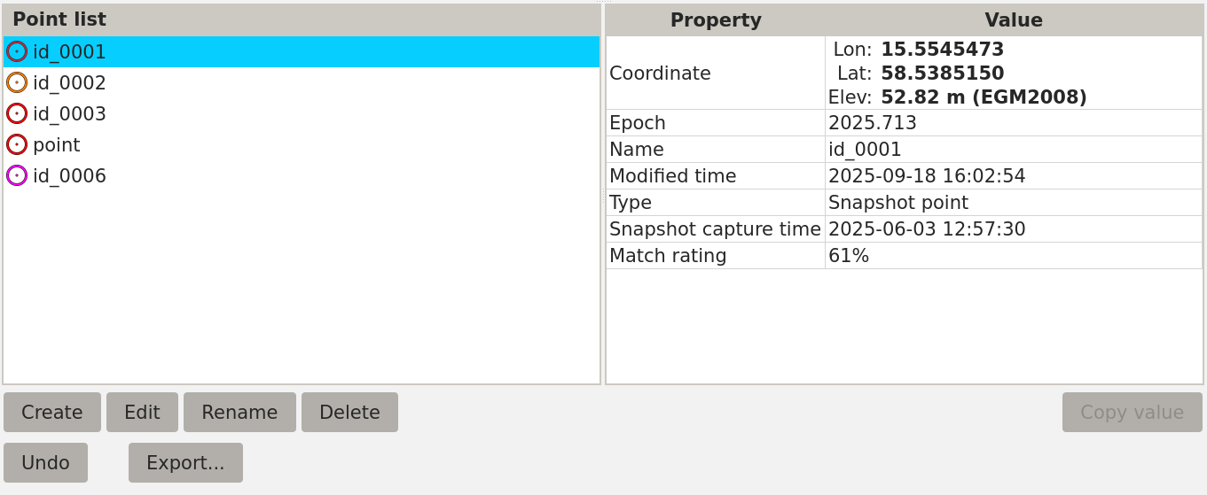
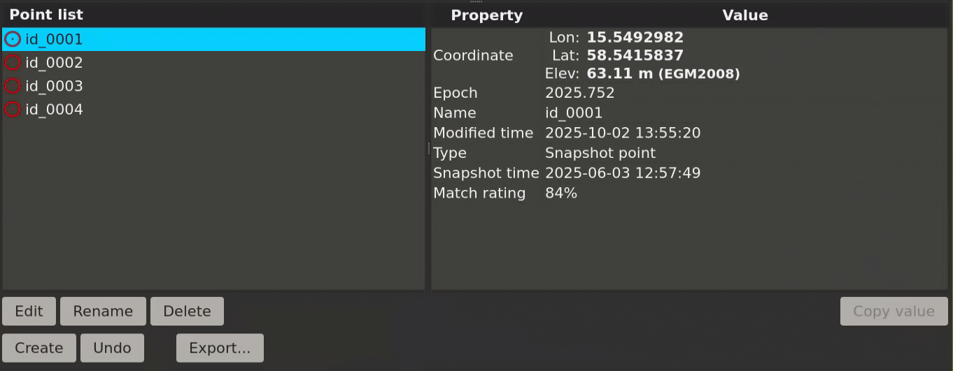
- Click Point list to see a list of saved points.
- Click a point in the left side list to display information about it.
- Click Create to create a new point.
- Click in the 3D data panel to place the point.
- Click Edit to edit an existing point.
- Click and drag the point in the 3D data panel to move the point to another position.
- Click Rename to change the name of a selected point.
- Click Delete to remove a selected point.
- Click Undo or use Ctrl+Z to revert the last point change.
- Click Export to export all point information to a JSON file and each point's video snapshot to PNG files.
- Click on any information in the information box to the right and then click Copy value to copy the information to the clipboard.
- 🔴 Red—Point extracted from the video panel.
- 🟠 Orange—Edited point initially extracted from the video panel.
- 🟣 Purple—Point manually created from the 3D data panel.